SPECTACLE BLINDS & BLEED RINGS
FIGURE 8 BLANKS
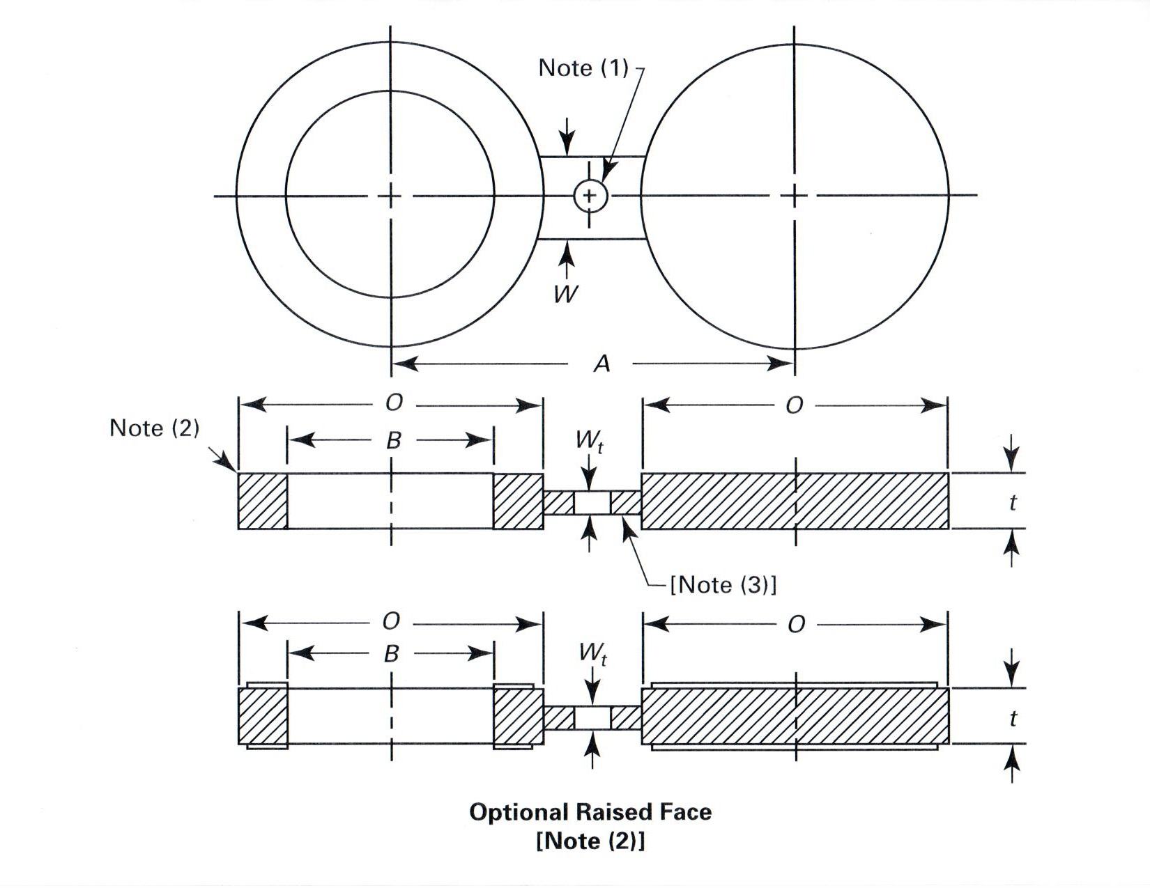 |
Dimension of Class 150 Raised Face Figure 8 Blanks
| NPS | Inside Diameter B |
Outside Diameter O |
Centerline Dimensions A |
Thickness t |
Web Width W |
|||||
| IN | MM | IN | MM | IN | MM | IN | MM | IN | MM | |
| ½ | .62 | 16 | 1.75 | 45 | 2.38 | 60 | .12 | 3.0 | 1.50 | 38 |
| ¾ | .82 | 21 | 2.12 | 54 | 2.75 | 70 | .12 | 3.0 | 1.50 | 38 |
| 1 | 1.05 | 27 | 2.50 | 64 | 3.12 | 80 | .12 | 3.0 | 1.50 | 38 |
| 1 ¼ | 1.66 | 42 | 2.88 | 73 | 3.50 | 90 | .25 | 6.4 | 1.50 | 38 |
| 1 ½ | 1.90 | 48 | 3.25 | 83 | 3.88 | 100 | .25 | 6.4 | 1.50 | 38 |
| 2 | 2.38 | 61 | 4.00 | 102 | 4.75 | 120 | .25 | 6.4 | 2.00 | 51 |
| 2 ½ | 2.88 | 73 | 4.75 | 107 | 5.50 | 140 | .25 | 6.4 | 2.00 | 51 |
| 3 | 3.50 | 89 | 5.25 | 133 | 6.00 | 150 | .25 | 6.4 | 2.50 | 64 |
| 3 ½ | 4.00 | 102 | 6.25 | 19 | 7.00 | 175 | .38 | 9.7 | 2.50 | 64 |
| 4 | 4.50 | 114 | 6.75 | 172 | 7.50 | 190 | .38 | 9.7 | 2.50 | 64 |
| 5 | 5.56 | 141 | 7.62 | 194 | 8.50 | 215 | .38 | 9.7 | 3.00 | 76 |
| 6 | 6.62 | 168 | 8.62 | 219 | 9.50 | 240 | .50 | 12.7 | 3.00 | 76 |
| 8 | 8.62 | 219 | 10.88 | 276 | 11.75 | 300 | .50 | 12.7 | 3.00 | 76 |
| 10 | 10.75 | 273 | 13.25 | 337 | 14.25 | 360 | .62 | 15.7 | 4.00 | 102 |
| 12 | 12.75 | 324 | 16.00 | 406 | 17.00 | 430 | .75 | 19.1 | 4.00 | 102 |
| 14 | 14.00 | 356 | 17.62 | 448 | 18.75 | 475 | .75 | 19.1 | 4.25 | 108 |
| 16 | 16.00 | 406 | 20.12 | 460 | 21.25 | 511 | .88 | 22.4 | 4.25 | 108 |
| 18 | 18.00 | 457 | 21.50 | 546 | 22.75 | 580 | 1.00 | 25.4 | 4.50 | 114 |
| 20 | 20.00 | 508 | 23.75 | 603 | 25.00 | 635 | 1.12 | 28.4 | 4.75 | 121 |
| 24 | 24.00 | 610 | 28.12 | 714 | 29.50 | 750 | 1.25 | 31.8 | 5.50 | 140 |
(2) Optional raised face. Refer to ASME B16.48 para. 4.3.1.
(3) The thickness of the web (or tie bar) dimension, Wt, shall be as determined by ASME B16.48 para.4.1.
Dimension of Class 300 Raised Face Figure 8 Blanks
| NPS | Inside Diameter B |
Outside Diameter O |
Centerline Dimensions A |
Thickness t |
Web Width W |
|||||
| IN | MM | IN | MM | IN | MM | IN | MM | IN | MM | |
| ½ | .62 | 16 | 2.00 | 51 | 2.62 | 65 | .25 | 6.4 | 1.50 | 38 |
| ¾ | .82 | 21 | 2.50 | 64 | 3.25 | 80 | .25 | 6.4 | 1.50 | 38 |
| 1 | 1.05 | 27 | 2.75 | 70 | 3.50 | 90 | .25 | 6.4 | 1.50 | 38 |
| 1 ¼ | 1.66 | 42 | 3.12 | 79 | 3.88 | 100 | .25 | 6.4 | 1.50 | 38 |
| 1 ½ | 1.90 | 48 | 3.62 | 92 | 4.50 | 115 | .25 | 6.4 | 1.50 | 38 |
| 2 | 2.38 | 61 | 4.25 | 108 | 5.00 | 125 | .38 | 9.7 | 2.00 | 51 |
| 2 ½ | 2.88 | 73 | 5.00 | 127 | 5.88 | 150 | .38 | 9.7 | 2.00 | 51 |
| 3 | 3.50 | 89 | 5.75 | 146 | 6.62 | 170 | .38 | 9.7 | 2.50 | 64 |
| 3 ½ | 4.00 | 102 | 6.38 | 162 | 7.25 | 185 | .50 | 12.7 | 2.50 | 64 |
| 4 | 4.50 | 114 | 7.00 | 178 | 7.88 | 200 | .50 | 12.7 | 2.50 | 64 |
| 5 | 5.56 | 141 | 8.38 | 213 | 9.25 | 235 | .62 | 15.7 | 3.00 | 76 |
| 6 | 6.62 | 168 | 9.75 | 248 | 10.62 | 270 | .62 | 15.7 | 3.00 | 76 |
| 8 | 8.62 | 219 | 12.00 | 305 | 13.00 | 330 | .88 | 22.4 | 3.00 | 76 |
| 10 | 10.75 | 273 | 14.12 | 359 | 15.25 | 385 | 1.00 | 25.4 | 4.00 | 102 |
| 12 | 12.75 | 324 | 16.50 | 419 | 17.750 | 450 | 1.12 | 28.4 | 4.00 | 102 |
| 14 | 14.00 | 356 | 19.00 | 483 | 20.25 | 515 | 1.25 | 31.8 | 4.25 | 108 |
| 16 | 16.00 | 406 | 21.12 | 536 | 22.50 | 570 | 1.50 | 38.1 | 4.25 | 108 |
| 18 | 18.00 | 457 | 23.38 | 594 | 24.75 | 630 | 1.62 | 41.1 | 4.50 | 114 |
| 20 | 20.00 | 508 | 25.62 | 651 | 27.00 | 685 | 1.75 | 44.5 | 4.75 | 121 |
| 24 | 24.00 | 610 | 30.38 | 772 | 32.00 | 810 | 2.00 | 50.8 | 5.50 | 140 |
(2) Optional raised face. Refer to ASME B16.48 para. 4.3.1.
(3) The thickness of the web (or tie bar) dimension, Wt, shall be as determined by ASME B16.48 para.4.1.
Dimension of Class 600 Raised Face Figure 8 Blanks
| NPS | Inside Diameter B |
Outside Diameter O |
Centerline Dimensions A |
Thickness t |
Web Width W |
|||||
| IN | MM | IN | MM | IN | MM | IN | MM | IN | MM | |
| ½ | .62 | 16 | 2.00 | 51 | 2.62 | 65 | .25 | 6.4 | 1.50 | 38 |
| ¾ | .82 | 21 | 2.50 | 64 | 3.25 | 80 | .25 | 6.4 | 1.50 | 38 |
| 1 | 1.05 | 27 | 2.75 | 70 | 3.50 | 90 | .25 | 6.4 | 2.25 | 57 |
| 1 ¼ | 1.44 | 37 | 3.12 | 79 | 3.88 | 100 | .38 | 9.7 | 2.25 | 57 |
| 1 ½ | 1.68 | 43 | 3.62 | 92 | 4.50 | 115 | .38 | 9.7 | 2.62 | 67 |
| 2 | 2.16 | 55 | 4.25 | 108 | 5.00 | 125 | .38 | 9.7 | 2.25 | 57 |
| 2 ½ | 2.64 | 67 | 5.00 | 127 | 5.88 | 150 | .50 | 12.7 | 2.62 | 67 |
| 3 | 3.26 | 83 | 5.75 | 146 | 6.62 | 170 | .50 | 12.7 | 2.62 | 67 |
| 3 ½ | 3.76 | 96 | 6.25 | 159 | 7.25 | 185 | .62 | 15.7 | 3.00 | 76 |
| 4 | 4.26 | 108 | 7.50 | 191 | 8.50 | 215 | .62 | 15.7 | 3.00 | 76 |
| 5 | 5.30 | 135 | 9.38 | 238 | 10.50 | 265 | .75 | 19.1 | 3.38 | 86 |
| 6 | 6.36 | 162 | 10.38 | 264 | 11.50 | 290 | .88 | 22.4 | 3.38 | 86 |
| 8 | 8.33 | 212 | 12.50 | 318 | 13.75 | 350 | 1.12 | 28.4 | 3.75 | 95 |
| 10 | 10.42 | 265 | 15.62 | 397 | 17.00 | 430 | 1.38 | 35.1 | 4.12 | 105 |
| 12 | 12.39 | 315 | 17.88 | 454 | 19.25 | 490 | 1.62 | 41.1 | 4.12 | 105 |
| 14 | 13.62 | 346 | 19.25 | 489 | 20.75 | 525 | 1.75 | 44.5 | 4.50 | 114 |
| 16 | 15.62 | 397 | 22.12 | 562 | 23.75 | 605 | 2.00 | 50.8 | 4.88 | 124 |
| 18 | 17.62 | 448 | 24.00 | 610 | 25.75 | 655 | 2.12 | 53.8 | 5.25 | 133 |
| 20 | 19.56 | 497 | 26.75 | 679 | 28.50 | 725 | 2.50 | 63.5 | 5.25 | 133 |
| 24 | 23.50 | 597 | 31.00 | 787 | 33.00 | 840 | 2.88 | 73.2 | 6.00 | 152 |
(2) Optional raised face. Refer to ASME B16.48 para. 4.3.1.
(3) The thickness of the web (or tie bar) dimension, Wt, shall be as determined by ASME B16.48 para.4.1.
Dimension of Class 900 Raised Face Figure 8 Blanks
| NPS | Inside Diameter B |
Outside Diameter O |
Centerline Dimensions A |
Thickness t |
Web Width W |
|||||
| IN | MM | IN | MM | IN | MM | IN | MM | IN | MM | |
| ½ | .62 | 16 | 2.38 | 60 | 3.25 | 80 | .25 | 6.4 | 1.50 | 38 |
| ¾ | .82 | 21 | 2.62 | 67 | 3.50 | 90 | .25 | 6.4 | 1.62 | 41 |
| 1 | 1.05 | 27 | 3.00 | 76 | 4.00 | 100 | .25 | 6.4 | 2.25 | 57 |
| 1 ¼ | 1.44 | 37 | 3.38 | 86 | 4.38 | 110 | .38 | 9.7 | 2.25 | 57 |
| 1 ½ | 1.68 | 43 | 3.75 | 95 | 4.88 | 125 | .38 | 9.7 | 2.62 | 67 |
| 2 | 2.16 | 55 | 5.50 | 140 | 6.50 | 165 | .50 | 12.7 | 2.25 | 57 |
| 2 ½ | 2.64 | 67 | 6.38 | 162 | 7.50 | 190 | .50 | 12.7 | 2.62 | 67 |
| 3 | 3.26 | 83 | 6.50 | 165 | 7.50 | 190 | .62 | 15.7 | 2.62 | 67 |
| 4 | 4.26 | 108 | 8.00 | 203 | 9.25 | 235 | .75 | 19.1 | 3.00 | 76 |
| 5 | 5.30 | 135 | 9.62 | 244 | 11.00 | 280 | .88 | 22.4 | 3.38 | 86 |
| 6 | 6.36 | 162 | 11.25 | 286 | 12.50 | 320 | 1.00 | 25.4 | 3.38 | 86 |
| 8 | 8.33 | 212 | 14.00 | 356 | 15.50 | 395 | 1.38 | 35.1 | 3.75 | 95 |
| 10 | 10.42 | 265 | 17.00 | 432 | 18.50 | 470 | 1.62 | 41.1 | 4.12 | 105 |
| 12 | 12.39 | 315 | 19.50 | 495 | 21.00 | 535 | 1.88 | 47.8 | 4.12 | 105 |
| 14 | 13.62 | 346 | 20.38 | 518 | 22.00 | 560 | 2.12 | 53.8 | 4.50 | 114 |
| 16 | 15.62 | 397 | 22.50 | 572 | 24.25 | 615 | 2.38 | 60.5 | 4.88 | 124 |
| 18 | 17.62 | 448 | 25.00 | 635 | 27.00 | 685 | 2.62 | 66.5 | 5.25 | 133 |
| 20 | 19.56 | 497 | 27.38 | 696 | 29.50 | 750 | 2.88 | 73.2 | 5.25 | 133 |
| 24 | 23.50 | 597 | 32.88 | 835 | 35.50 | 900 | 3.50 | 88.9 | 6.00 | 152 |
(2) Optional raised face. Refer to ASME B16.48 para. 4.3.1.
(3) The thickness of the web (or tie bar) dimension, Wt, shall be as determined by ASME B16.48 para.4.1.
Dimension of Class 1500 Raised Face Figure 8 Blanks
| NPS | Inside Diameter B |
Outside Diameter O |
Centerline Dimensions A |
Thickness t |
Web Width W |
|||||
| IN | MM | IN | MM | IN | MM | IN | MM | IN | MM | |
| ½ | .62 | 16 | 2.38 | 60 | 3.25 | 80 | .25 | 6.4 | 1.50 | 38 |
| ¾ | .82 | 21 | 2.62 | 67 | 3.50 | 90 | .38 | 9.7 | 1.62 | 41 |
| 1 | 1.05 | 27 | 3.00 | 76 | 4.00 | 100 | .38 | 9.7 | 2.20 | 64 |
| 1 ¼ | 1.38 | 35 | 3.38 | 86 | 4.38 | 110 | .38 | 9.7 | 2.50 | 64 |
| 1 ½ | 1.61 | 41 | 3.75 | 95 | 4.88 | 125 | .50 | 12.7 | 2.75 | 70 |
| 2 | 2.07 | 53 | 5.50 | 140 | 6.50 | 165 | .50 | 12.7 | 2.75 | 70 |
| 2 ½ | 2.47 | 63 | 6.38 | 162 | 7.50 | 190 | .62 | 15.7 | 3.00 | 76 |
| 3 | 3.07 | 78 | 6.75 | 172 | 8.00 | 205 | .75 | 19.1 | 3.00 | 76 |
| 4 | 4.03 | 102 | 8.12 | 206 | 9.50 | 240 | .88 | 22.4 | 3.50 | 89 |
| 5 | 5.05 | 128 | 9.88 | 251 | 11.50 | 290 | 1.12 | 28.4 | 3.50 | 89 |
| 6 | 6.06 | 154 | 11.00 | 279 | 12.50 | 320 | 1.38 | 35.1 | 3.50 | 89 |
| 8 | 7.98 | 203 | 13.75 | 349 | 15.50 | 395 | 1.62 | 41.1 | 4.00 | 102 |
| 10 | 10.02 | 255 | 17.00 | 432 | 19.00 | 480 | 2.00 | 50.8 | 4.50 | 114 |
| 12 | 11.94 | 303 | 20.38 | 518 | 22.50 | 570 | 2.38 | 60.5 | 4.50 | 114 |
| 14 | 13.12 | 333 | 22.62 | 575 | 25.00 | 635 | 2.62 | 66.5 | 5.00 | 127 |
| 16 | 15.00 | 381 | 25.12 | 638 | 27.75 | 705 | 3.00 | 76.2 | 5.25 | 133 |
| 18 | 16.88 | 429 | 27.62 | 702 | 30.50 | 775 | 3.38 | 85.9 | 5.75 | 146 |
| 20 | 18.81 | 478 | 29.62 | 752 | 32.75 | 830 | 3.75 | 95.3 | 6.00 | 152 |
| 24 | 22.62 | 575 | 35.38 | 899 | 39.00 | 990 | 4.38 | 111.3 | 7.00 | 178 |
(2) Optional raised face. Refer to ASME B16.48 para. 4.3.1.
(3) The thickness of the web (or tie bar) dimension, Wt, shall be as determined by ASME B16.48 para.4.1.
Dimension of Class 2500 Raised Face Figure 8 Blanks
| NPS | Inside Diameter B |
Outside Diameter O |
Centerline Dimensions A |
Thickness t |
Web Width W |
|||||
| IN | MM | IN | MM | IN | MM | IN | MM | IN | MM | |
| ½ | .62 | 16 | 2.62 | 67 | 3.50 | 90 | .38 | 9.7 | 1.50 | 38 |
| ¾ | .82 | 21 | 2.88 | 73 | 3.75 | 95 | .38 | 9.7 | 1.62 | 41 |
| 1 | 1.05 | 27 | 3.25 | 83 | 4.25 | 110 | .38 | 9.7 | 2.50 | 64 |
| 1 ¼ | 1.38 | 35 | 4.00 | 102 | 5.12 | 130 | .50 | 12.7 | 2.50 | 64 |
| 1 ½ | 1.61 | 41 | 4.50 | 114 | 5.75 | 145 | .62 | 15.7 | 2.75 | 70 |
| 2 | 2.07 | 53 | 5.62 | 143 | 6.75 | 170 | .62 | 15.7 | 2.75 | 70 |
| 2 ½ | 2.47 | 63 | 6.50 | 165 | 7.75 | 195 | .75 | 19.1 | 3.00 | 76 |
| 3 | 3.07 | 78 | 7.62 | 194 | 9.00 | 230 | .88 | 22.4 | 3.00 | 76 |
| 4 | 4.03 | 102 | 9.12 | 232 | 10.75 | 275 | 1.12 | 28.4 | 3.50 | 89 |
| 5 | 5.05 | 128 | 10.88 | 276 | 12.75 | 325 | 1.38 | 35.1 | 3.50 | 89 |
| 6 | 6.06 | 154 | 12.38 | 314 | 14.50 | 370 | 1.62 | 41.1 | 3.50 | 89 |
| 8 | 7.81 | 198 | 15.12 | 384 | 17.25 | 440 | 2.12 | 53.8 | 4.00 | 102 |
| 10 | 9.75 | 248 | 18.62 | 473 | 21.25 | 540 | 2.62 | 66.5 | 4.50 | 114 |
| 12 | 11.37 | 289 | 21.50 | 546 | 24.38 | 620 | 3.12 | 79.2 | 4.50 | 114 |
(2) Optional raised face. Refer to ASME B16.48 para. 4.3.1.
(3) The thickness of the web (or tie bar) dimension, Wt, shall be as determined by ASME B16.48 para.4.1.
FIGURE 8 RING JOINT BLANKS
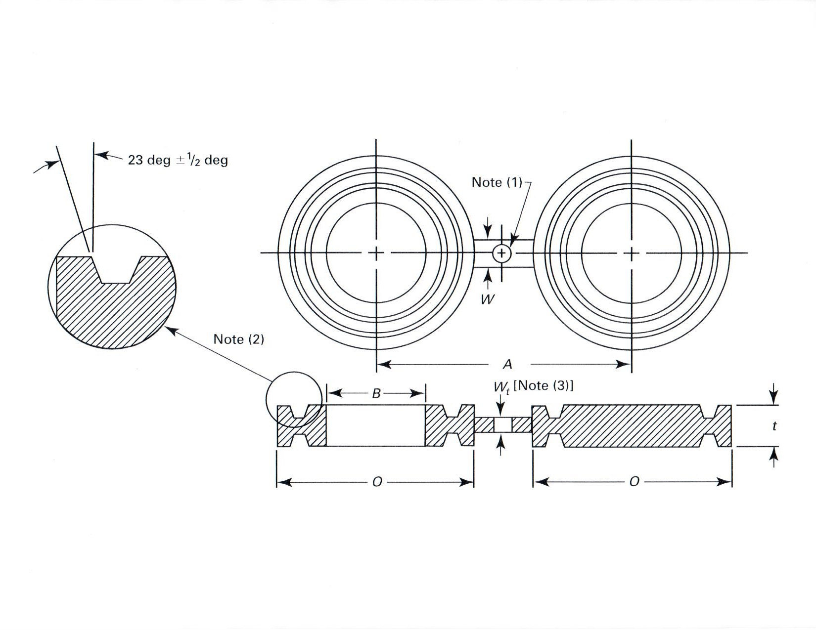 |
Dimension of Class 150 Female Ring Joint Facing Figure 8 Blanks
| NPS | Inside Diameter B |
Outside Diameter O |
Centerline Dimensions A |
Thickness t |
Web Width W |
|||||
| IN | MM | IN | MM | IN | MM | IN | MM | IN | MM | |
| 1 | 1.32 | 34 | 2.50 | 64 | 3.12 | 80 | .75 | 19.1 | 2.00 | 51 |
| 1 ¼ | 1.66 | 42 | 2.88 | 73 | 3.50 | 90 | .75 | 19.1 | 2.00 | 51 |
| 1 ½ | 1.90 | 48 | 3.25 | 83 | 3.88 | 100 | .75 | 19.1 | 2.25 | 57 |
| 2 | 2.38 | 61 | 4.00 | 102 | 4.75 | 120 | .75 | 19.1 | 2.25 | 57 |
| 2 ½ | 2.88 | 73 | 4.75 | 121 | 5.50 | 140 | .88 | 22.4 | 2.25 | 57 |
| 3 | 3.50 | 89 | 5.25 | 133 | 6.00 | 150 | .88 | 22.4 | 2.25 | 57 |
| 3 ½ | 4.00 | 102 | 6.06 | 154 | 7.00 | 175 | .88 | 22.4 | 2.50 | 64 |
| 4 | 4.50 | 114 | 6.75 | 172 | 7.50 | 190 | .88 | 22.4 | 2.50 | 64 |
| 5 | 5.56 | 141 | 7.62 | 194 | 8.50 | 215 | 1.00 | 25.4 | 2.75 | 70 |
| 6 | 6.62 | 168 | 8.62 | 219 | 9.50 | 240 | 1.00 | 25.4 | 3.25 | 83 |
| 8 | 8.62 | 219 | 10.75 | 273 | 11.75 | 300 | 1.12 | 28.4 | 3.75 | 95 |
| 10 | 10.75 | 273 | 13.00 | 330 | 14.25 | 360 | 1.25 | 31.8 | 4.00 | 102 |
| 12 | 12.75 | 324 | 16.00 | 406 | 17.00 | 430 | 1.38 | 35.1 | 4.75 | 121 |
| 14 | 14.00 | 256 | 16.75 | 426 | 18.75 | 475 | 1.38 | 35.1 | 5.00 | 127 |
| 16 | 16.00 | 406 | 19.00 | 483 | 21.25 | 540 | 1.50 | 38.1 | 5.00 | 127 |
| 18 | 18.00 | 457 | 21.50 | 546 | 22.75 | 580 | 1.62 | 41.1 | 5.00 | 127 |
| 20 | 20.00 | 508 | 23.50 | 597 | 25.00 | 635 | 1.62 | 41.1 | 5.00 | 127 |
| 24 | 24.00 | 610 | 28.00 | 711 | 29.50 | 750 | 1.88 | 47.8 | 6.00 | 152 |
(2) Female ring-joint groove dimensions shall be in accordance with ASME B16.5.
(3) The thickness of the web (or tie bar) dimension, Wt, shall be as determined by ASME B16.48 para.4.1.
Dimension of Class 300 Female Ring Joint Facing Figure 8 Blanks
| NPS | Inside Diameter B |
Outside Diameter O |
Centerline Dimensions A |
Thickness t |
Web Width W |
|||||
| IN | MM | IN | MM | IN | MM | IN | MM | IN | MM | |
| ½ | .84 | 21 | 2.00 | 51 | 2.62 | 65 | .62 | 15.7 | 1.50 | 38 |
| ¾ | 1.05 | 27 | 2.50 | 64 | 3.25 | 80 | .75 | 19.1 | 1.75 | 45 |
| 1 | 1.32 | 34 | 2.75 | 70 | 3.50 | 90 | .75 | 19.1 | 2.00 | 51 |
| 1 ¼ | 1.66 | 42 | 3.12 | 79 | 3.88 | 100 | .88 | 22.4 | 2.00 | 51 |
| 1 ½ | 1.90 | 48 | 3.56 | 90 | 4.50 | 115 | .88 | 22.4 | 2.25 | 57 |
| 2 | 2.38 | 61 | 4.25 | 108 | 5.00 | 125 | 1.00 | 25.4 | 2.25 | 57 |
| 2 ½ | 2.88 | 73 | 5.00 | 127 | 5.88 | 150 | 1.12 | 28.4 | 2.25 | 57 |
| 3 | 3.50 | 89 | 5.75 | 146 | 6.62 | 170 | 1.12 | 28.4 | 2.25 | 57 |
| 3 ½ | 4.00 | 102 | 6.25 | 159 | 7.25 | 185 | 1.12 | 28.4 | 2.50 | 64 |
| 4 | 4.50 | 114 | 6.88 | 175 | 7.88 | 200 | 1.25 | 31.8 | 2.50 | 64 |
| 5 | 5.56 | 141 | 8.25 | 210 | 9.25 | 235 | 1.38 | 35.1 | 2.75 | 70 |
| 6 | 6.62 | 168 | 9.50 | 241 | 10.62 | 270 | 1.38 | 35.1 | 3.25 | 83 |
| 8 | 8.62 | 219 | 11.88 | 302 | 13.00 | 330 | 1.62 | 41.1 | 3.75 | 95 |
| 10 | 10.75 | 273 | 14.00 | 356 | 15.25 | 385 | 1.75 | 44.5 | 4.00 | 102 |
| 12 | 12.75 | 324 | 16.25 | 413 | 17.75 | 450 | 2.00 | 50.8 | 4.75 | 121 |
| 14 | 14.00 | 356 | 18.00 | 457 | 20.25 | 515 | 2.12 | 53.8 | 5.00 | 127 |
| 16 | 16.00 | 406 | 20.00 | 508 | 22.50 | 570 | 2.25 | 57.2 | 5.00 | 127 |
| 18 | 18.00 | 457 | 22.62 | 575 | 24.75 | 630 | 2.38 | 60.5 | 5.00 | 127 |
| 20 | 20.00 | 508 | 25.00 | 635 | 27.00 | 685 | 2.75 | 69.9 | 5.00 | 127 |
| 24 | 24.00 | 610 | 29.50 | 749 | 32.00 | 810 | 3.12 | 79.2 | 6.00 | 152 |
(2) Female ring-joint groove dimensions shall be in accordance with ASME B16.5.
(3) The thickness of the web (or tie bar) dimension, Wt, shall be as determined by ASME B16.48 para.4.1.
Dimension of Class 600 Female Ring Joint Facing Figure 8 Blanks
| NPS | Inside Diameter B |
Outside Diameter O |
Centerline Dimensions A |
Thickness t |
Web Width W |
|||||
| IN | MM | IN | MM | IN | MM | IN | MM | IN | MM | |
| ½ | .84 | 21 | 2.00 | 51 | 2.62 | 65 | .75 | 19.1 | 1.50 | 38 |
| ¾ | 1.05 | 27 | 2.50 | 64 | 3.25 | 80 | .88 | 22.4 | 1.75 | 45 |
| 1 | 1.32 | 34 | 2.75 | 70 | 3.50 | 90 | .88 | 22.4 | 2.00 | 51 |
| 1 ¼ | 1.66 | 42 | 3.12 | 79 | 3.88 | 100 | .88 | 22.4 | 2.00 | 51 |
| 1 ½ | 1.90 | 48 | 3.56 | 90 | 4.50 | 115 | .88 | 22.4 | 2.25 | 57 |
| 2 | 2.38 | 61 | 4.25 | 108 | 5.00 | 125 | 1.12 | 28.4 | 2.25 | 57 |
| 2 ½ | 2.88 | 73 | 5.00 | 127 | 5.88 | 150 | 1.25 | 31.8 | 2.25 | 57 |
| 3 | 3.50 | 89 | 5.75 | 146 | 6.62 | 170 | 1.25 | 31.8 | 2.25 | 57 |
| 3 ½ | 4.00 | 102 | 6.25 | 159 | 7.25 | 185 | 1.38 | 35.1 | 2.50 | 64 |
| 4 | 4.50 | 114 | 6.88 | 175 | 8.50 | 215 | 1.38 | 35.1 | 2.50 | 64 |
| 5 | 5.56 | 141 | 8.25 | 210 | 10.50 | 265 | 1.50 | 38.1 | 2.75 | 70 |
| 6 | 6.62 | 168 | 9.50 | 241 | 11.50 | 290 | 1.75 | 44.5 | 3.25 | 83 |
| 8 | 8.62 | 219 | 11.88 | 302 | 13.75 | 350 | 2.00 | 50.8 | 3.75 | 95 |
| 10 | 10.75 | 273 | 14.00 | 356 | 17.00 | 430 | 2.25 | 57.2 | 4.00 | 102 |
| 12 | 12.75 | 324 | 16.25 | 413 | 19.25 | 490 | 2.50 | 63.5 | 4.75 | 121 |
| 14 | 14.00 | 356 | 18.00 | 457 | 20.75 | 525 | 2.62 | 66.5 | 5.00 | 127 |
| 16 | 16.00 | 406 | 20.00 | 508 | 23.75 | 605 | 2.88 | 73.2 | 5.00 | 127 |
| 18 | 18.00 | 457 | 22.62 | 575 | 25.75 | 655 | 3.12 | 79.2 | 5.00 | 127 |
| 20 | 20.00 | 508 | 25.00 | 635 | 28.50 | 725 | 3.50 | 88.9 | 5.00 | 127 |
| 24 | 24.00 | 610 | 29.50 | 749 | 33.00 | 840 | 4.12 | 104.6 | 6.00 | 152 |
(2) Female ring-joint groove dimensions shall be in accordance with ASME B16.5.
(3) The thickness of the web (or tie bar) dimension, Wt, shall be as determined by ASME B16.48 para.4.1.
Dimension of Class 900 Female Ring Joint Facing Figure 8 Blanks
| NPS | Inside Diameter B |
Outside Diameter O |
Centerline Dimensions A |
Thickness t |
Web Width W |
|||||
| IN | MM | IN | MM | IN | MM | IN | MM | IN | MM | |
| ½ | .84 | 21 | 2.38 | 61 | 3.25 | 80 | .88 | 22.4 | 1.50 | 38 |
| ¾ | 1.05 | 27 | 2.62 | 67 | 3.50 | 90 | .88 | 22.4 | 1.75 | 45 |
| 1 | 1.32 | 34 | 2.81 | 71 | 4.00 | 100 | .88 | 22.4 | 2.00 | 51 |
| 1 ¼ | 1.66 | 42 | 3.19 | 81 | 4.38 | 110 | 1.00 | 25.4 | 2.00 | 51 |
| 1 ½ | 1.90 | 48 | 3.62 | 92 | 4.88 | 125 | 1.00 | 25.4 | 2.50 | 64 |
| 2 | 2.38 | 61 | 4.88 | 124 | 6.50 | 165 | 1.25 | 31.8 | 2.00 | 51 |
| 2 ½ | 2.88 | 73 | 5.38 | 137 | 7.50 | 190 | 1.38 | 35.1 | 2.62 | 67 |
| 3 | 3.50 | 89 | 6.12 | 155 | 7.50 | 190 | 1.38 | 35.1 | 2.62 | 67 |
| 4 | 4.50 | 114 | 7.12 | 181 | 9.25 | 235 | 1.62 | 41.1 | 2.88 | 73 |
| 5 | 5.56 | 141 | 8.50 | 216 | 11.00 | 280 | 1.75 | 44.5 | 2.88 | 73 |
| 6 | 6.62 | 168 | 9.50 | 241 | 12.50 | 315 | 1.88 | 47.8 | 2.88 | 73 |
| 8 | 8.62 | 219 | 12.12 | 308 | 15.50 | 395 | 2.25 | 57.2 | 3.12 | 80 |
| 10 | 10.75 | 273 | 14.25 | 362 | 18.50 | 470 | 2.50 | 63.5 | 4.75 | 121 |
| 12 | 12.75 | 324 | 16.50 | 419 | 21.00 | 535 | 2.88 | 73.2 | 4.75 | 121 |
| 14 | 14.00 | 356 | 18.38 | 467 | 22.00 | 560 | 3.25 | 82.6 | 4.75 | 121 |
| 16 | 16.00 | 406 | 20.62 | 524 | 24.25 | 615 | 3.62 | 91.9 | 5.00 | 127 |
| 18 | 18.00 | 457 | 23.38 | 594 | 27.00 | 685 | 4.00 | 101.6 | 5.25 | 133 |
| 20 | 20.00 | 508 | 25.50 | 648 | 29.50 | 750 | 4.38 | 111.3 | 5.00 | 127 |
| 24 | 24.00 | 610 | 30.38 | 772 | 35.50 | 900 | 5.25 | 133.4 | 5.50 | 140 |
(2) Female ring-joint groove dimensions shall be in accordance with ASME B16.5.
(3) The thickness of the web (or tie bar) dimension, Wt, shall be as determined by ASME B16.48 para.4.1.
Dimension of Class 1500 Female Ring Joint Facing Figure 8 Blanks
| NPS | Inside Diameter B |
Outside Diameter O |
Centerline Dimensions A |
Thickness t |
Web Width W |
|||||
| IN | MM | IN | MM | IN | MM | IN | MM | IN | MM | |
| ½ | .84 | 21 | 2.38 | 61 | 3.25 | 80 | .88 | 22.4 | 1.50 | 38 |
| ¾ | 1.05 | 27 | 2.62 | 67 | 3.50 | 90 | 1.00 | 25.4 | 1.75 | 45 |
| 1 | 1.32 | 34 | 2.81 | 71 | 4.00 | 100 | 1.00 | 25.4 | 2.12 | 54 |
| 1 ¼ | 1.66 | 42 | 3.19 | 81 | 4.38 | 110 | 1.00 | 25.4 | 2.12 | 54 |
| 1 ½ | 1.90 | 48 | 3.62 | 92 | 4.88 | 125 | 1.12 | 28.4 | 2.25 | 57 |
| 2 | 2.38 | 61 | 4.88 | 124 | 6.50 | 165 | 1.38 | 35.1 | 2.12 | 54 |
| 2 ½ | 2.88 | 73 | 5.38 | 137 | 7.50 | 190 | 1.50 | 38.1 | 2.25 | 57 |
| 3 | 3.50 | 89 | 6.62 | 168 | 8.00 | 205 | 1.75 | 44.5 | 2.88 | 73 |
| 4 | 4.50 | 114 | 7.62 | 194 | 9.50 | 240 | 1.88 | 47.8 | 3.00 | 76 |
| 5 | 5.56 | 141 | 9.00 | 229 | 11.50 | 290 | 2.12 | 53.8 | 3.00 | 76 |
| 6 | 6.62 | 168 | 9.75 | 248 | 12.50 | 315 | 2.38 | 60.5 | 3.12 | 79 |
| 8 | 8.62 | 219 | 12.50 | 318 | 15.50 | 395 | 2.88 | 73.2 | 3.38 | 86 |
| 10 | 10.75 | 273 | 14.62 | 371 | 19.00 | 480 | 3.25 | 82.5 | 5.25 | 133 |
| 12 | 12.75 | 324 | 17.25 | 438 | 22.50 | 570 | 4.00 | 101.6 | 5.25 | 133 |
| 14 | 14.00 | 356 | 19.25 | 489 | 25.00 | 635 | 4.38 | 111.3 | 5.50 | 140 |
| 16 | 16.00 | 406 | 21.50 | 546 | 27.75 | 705 | 4.88 | 124.0 | 5.75 | 146 |
| 18 | 18.00 | 457 | 24.12 | 613 | 30.50 | 775 | 5.25 | 133.0 | 6.00 | 152 |
| 20 | 20.00 | 508 | 26.50 | 673 | 32.75 | 830 | 5.62 | 142.7 | 6.50 | 165 |
| 24 | 24.00 | 610 | 31.25 | 794 | 39.00 | 990 | 6.62 | 168.1 | 7.00 | 178 |
(2) Female ring-joint groove dimensions shall be in accordance with ASME B16.5.
(3) The thickness of the web (or tie bar) dimension, Wt, shall be as determined by ASME B16.48 para.4.1.
Dimension of Class 2500 Female Ring Joint Facing Figure 8 Blanks
| NPS | Inside Diameter B |
Outside Diameter O |
Centerline Dimensions A |
Thickness t |
Web Width W |
|||||
| IN | MM | IN | MM | IN | MM | IN | MM | IN | MM | |
| ½ | .84 | 21 | 2.56 | 65 | 3.50 | 90 | 1.00 | 25.4 | 1.50 | 38 |
| ¾ | 1.05 | 27 | 2.88 | 73 | 3.75 | 95 | 1.12 | 28.4 | 1.75 | 45 |
| 1 | 1.32 | 34 | 3.25 | 83 | 4.25 | 110 | 1.12 | 28.4 | 2.12 | 54 |
| 1 ¼ | 1.66 | 42 | 4.00 | 102 | 5.12 | 130 | 1.38 | 35.1 | 2.12 | 54 |
| 1 ½ | 1.90 | 48 | 4.50 | 114 | 5.75 | 145 | 1.50 | 38.1 | 2.38 | 61 |
| 2 | 2.38 | 61 | 5.25 | 133 | 6.75 | 170 | 1.62 | 41.1 | 2.25 | 57 |
| 2 ½ | 2.88 | 73 | 5.88 | 149 | 7.75 | 195 | 1.88 | 47.8 | 2.38 | 61 |
| 3 | 3.50 | 89 | 6.62 | 168 | 9.00 | 230 | 2.00 | 50.8 | 3.00 | 76 |
| 4 | 4.50 | 114 | 8.00 | 203 | 10.75 | 270 | 2.50 | 63.5 | 3.25 | 83 |
| 5 | 5.56 | 141 | 9.50 | 241 | 12.75 | 325 | 2.88 | 73.2 | 3.50 | 89 |
| 6 | 6.62 | 168 | 11.00 | 279 | 14.50 | 370 | 3.25 | 82.6 | 3.75 | 95 |
| 8 | 8.62 | 219 | 13.38 | 340 | 17.25 | 440 | 3.88 | 98.6 | 3.75 | 95 |
| 10 | 10.75 | 273 | 16.75 | 425 | 21.25 | 540 | 4.62 | 117.3 | 3.58 | 91 |
| 12 | 12.75 | 324 | 19.50 | 495 | 24.38 | 620 | 5.25 | 133.4 | 6.00 | 152 |
(2) Female ring-joint groove dimensions shall be in accordance with ASME B16.5.
(3) The thickness of the web (or tie bar) dimension, Wt, shall be as determined by ASME B16.48 para.4.1.
BLEED RINGS
 |
|||||||||||||||
| Dimension in Inches | |||||||||||||
| NPS | 150 | 300 | 600 | 900 | 1500 | 2500 | |||||||
| A | B | A | B | A | B | A | B | A | B | A | B | ||
| 1 | 1.05 | 2.50 | 1.05 | 2.75 | 1.05 | 2.75 | 1.05 | 3.00 | 1.05 | 3.00 | 1.05 | 3.25 | |
| 1 ½ | 1.90 | 3.25 | 1.90 | 3.62 | 1.68 | 3.62 | 1.44 | 3.75 | 1.61 | 3.75 | 1.61 | 4.50 | |
| 2 | 2.38 | 4.00 | 2.38 | 4.25 | 2.16 | 4.25 | 2.16 | 5.50 | 2.07 | 5.50 | 2.07 | 5.62 | |
| 2 ½ | 2.88 | 4.75 | 2.88 | 5.00 | 2.64 | 5.00 | 2.64 | 6.38 | 2.47 | 6.38 | 2.47 | 6.50 | |
| 3 | 3.50 | 5.25 | 3.50 | 5.75 | 3.26 | 5.75 | 3.26 | 6.50 | 3.07 | 6.75 | 3.07 | 7.62 | |
| 4 | 4.50 | 6.75 | 4.50 | 7.00 | 4.26 | 7.50 | 4.26 | 8.00 | 4.03 | 8.12 | 4.03 | 9.12 | |
| 5 | 5.56 | 7.62 | 5.56 | 8.38 | 5.30 | 9.38 | 5.30 | 9.62 | 5.05 | 9.88 | 5.05 | 10.88 | |
| 6 | 6.62 | 8.62 | 6.62 | 9.75 | 6.36 | 10.38 | 6.36 | 11.25 | 6.06 | 11.00 | 6.06 | 12.38 | |
| 8 | 8.62 | 10.88 | 8.62 | 12.00 | 8.33 | 12.50 | 8.33 | 14.00 | 7.98 | 13.75 | 7.81 | 15.12 | |
| 10 | 10.75 | 13.25 | 10.75 | 14.12 | 10.42 | 15.62 | 10.42 | 17.00 | 10.02 | 17.00 | 9.75 | 18.62 | |
| 12 | 12.75 | 16.00 | 12.75 | 16.50 | 12.39 | 17.88 | 12.39 | 19.50 | 11.94 | 20.38 | 11.37 | 21.50 | |
| 14 | 14.00 | 17.62 | 14.00 | 19.00 | 13.62 | 19.25 | 13.62 | 20.38 | 13.12 | 22.62 | |||
| 16 | 16.00 | 20.12 | 16.00 | 21.12 | 15.62 | 22.12 | 15.62 | 22.50 | 15.00 | 25.12 | |||
| 18 | 18.00 | 21.50 | 18.00 | 23.38 | 17.62 | 24.00 | 17.62 | 25.00 | 16.88 | 27.62 | |||
| 20 | 20.00 | 23.75 | 20.00 | 25.62 | 19.56 | 26.75 | 19.56 | 27.38 | 18.81 | 29.62 | |||
| 24 | 24.00 | 28.12 | 24.00 | 30.38 | 23.50 | 31.00 | 23.50 | 32.88 | 22.62 | 35.38 | |||
(1/2” NPT + 7/8”) – (3/4” NPT + 1”) – (1” NPT + 1-3/8”)
(2) Bleed Rings with 1" NPT shall be 2" thick.
VOP Addendum 1 to ASME B16.48
| Home | News | Products | Swages | Oil Country | Couplings | Spec Blinds | Gapalets | Ring Gaskets | Needle Valves | Pressure Gauges | Hammer Unions | Swivel Joints | API Flanges | Chokes | Catalogues |
Send mail to Webmaster
with questions or comments about this web site.
Copyright © 2024 Vengeance Oilfield Products Inc